By the Baoluo Motor Engineering Team · Published 2026-10-10
A customer called us about an electric forklift that would not run. The AC traction motor would jerk once, then the AC motor controller would throw an overcurrent alarm and shut down. The speed readout on the display stayed at zero. They had already swapped nothing and assumed the motor was dead. It was not. The fault sat in the pairing between the motor's encoder and the controller, and it is one of the most common ways an AC drive system gets blamed for a problem it did not start.
This guide walks through what we found on that job, how we fixed it, and the other AC motor and controller matching faults we see most often. If you run three phase induction motor drives in electric forklifts, tow tractors, AGVs or other material handling equipment, the checklist at the end is the part to keep.
Rule of thumb: when a controller reports overcurrent and also loses the speed signal at the same time, suspect the feedback path before the motor. A motor that is mechanically free and electrically sound does not trip the drive and kill the speed readout in the same breath. The two symptoms together point at the encoder-to-controller link.
1. What the machine was doing
The unit was an XYQ-series AC asynchronous traction motor on a standard B5 flange, rated for a 48 V DC battery supply, with a Hall-effect (magnetic) incremental encoder on the rear shaft. The controller was our C750-series AC motor controller. On the customer's floor the sequence was always the same: power on, a brief jerk from the motor, controller alarm, dead stop.
The customer had already ruled out the obvious mechanical things on their own. The wheels turned freely by hand. There was no burnt smell, no smoke, no bearing noise. That last point mattered, because a motor that turns freely by hand and still trips the drive is rarely a mechanical problem.
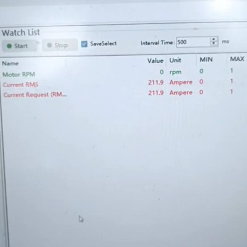
2. What the controller was telling us
Two fault signals came up together on the controller status screen, and reading them as a pair is what narrowed the search:
- Abnormal current. The controller reported an overcurrent event the moment it tried to spin the motor up.
- No speed feedback. The speed value stayed at zero even though the shaft was moving. The controller could not see how fast the motor was turning.
Those two together are a specific fingerprint. A closed-loop AC drive needs the speed signal from the encoder to control current. If the drive cannot read the speed, its current loop runs blind. It either faults on "feedback missing" or pushes current it cannot regulate, which shows up exactly as an overcurrent alarm. The motor was not drawing too much current on its own. The controller was losing its eyes and over-reacting.
The same pattern shows up across brands. Drives running closed-loop vector control with an encoder or resolver will fault on a missing or corrupted feedback signal, and the secondary symptom is almost always a current-related trip. We see it on forklifts, electric tow tractors and AGVs alike.
3. The real cause: the Hall encoder and the controller were not matched
An AC traction motor and its controller are not two separate products that happen to be bolted together. The international standard IEC 61800, which covers adjustable speed electrical power drive systems, treats the drive, the motor and the feedback device (encoder or resolver) as one integrated system. Get any one of those three mismatched and the system misbehaves even when every part is individually healthy.
In this case the motor carried a Hall-effect encoder at 64 pulses per revolution. The controller software on the unit did not have the configuration profile for that encoder type, and the wiring harness definition (the pinout that tells the controller which wire is which) did not match what the motor's encoder actually presented. So the controller saw a signal it could not decode, reported no speed, ran its current loop open, and tripped on overcurrent. No component was broken. The pairing was wrong.
This is the step most people skip. They swap the motor or the drive, see the same fault, and conclude the replacement is also bad. The fault was in the match, not in the metal.
4. How we fixed it
Two changes solved it, and neither involved replacing a motor or a controller:
- Controller software (firmware) upgrade. We loaded the controller firmware version that includes the configuration profile for this Hall encoder type. The drive then knew how to read the sensor and derive a speed signal.
- Reassigning the wiring harness definition. We re-mapped the harness so the Hall power, the A/B channels and the index channel landed on the pins the controller expected. The physical wires were fine; the definition of what each wire meant was not.
After the upgrade and the re-pinout, the speed readout came alive, the current trace settled into its normal band, and the forklift ran. The whole fix took less time than swapping a motor would have, and it left the customer with the original hardware intact.
If your fault is inside the winding rather than in the pairing, that is a different job. We cover the winding failure that a meter cannot find in our stator inter-turn short guide.
5. The other AC motor and controller matching faults
The Hall encoder mismatch above is only one of the ways an AC motor and its controller refuse to get along. Here are the others we meet most, with the standard that backs each one up.
| Fault mode | What you see | Why it happens | Fix |
|---|---|---|---|
| Encoder or resolver type not configured in the drive | No speed feedback, overcurrent, "feedback missing" alarm | The drive, motor and feedback are one system under IEC 61800. The drive must be told what sensor it is reading. | Load the firmware profile for the encoder type and match the harness definition. |
| Motor nameplate data entered wrong | Weak torque, unstable current, trips under load | Pole count, rated voltage and frequency, and rated current set wrongly make the drive calculate field and slip incorrectly (IEC 61800-1). | Enter the correct nameplate parameters. Motors we supply ship with the data ready to load. |
| Inverter voltage overshoot stressing the winding | Random trips, then winding failure weeks later | Fast switching from the drive sends voltage spikes and steep dV/dt to the motor terminals. IEC 60034-25:2022 and NEMA MG-1 Part 31 cover converter-duty motors and this exact stress. | Use a converter-duty (inverter-rated) motor and match the drive overshoot to the motor insulation. |
| Controller current rating below motor demand | Overcurrent trips the moment load appears | The controller cannot sustain the motor's continuous or peak current. Our C750 controllers are sized with peak current to spare. | Size the controller to the motor's continuous and peak current, not just its rated power. |
| Encoder or motor cable shielding and grounding wrong | Intermittent speed errors, current spikes, random trips | Unfiltered noise fools the speed loop. IEC 61800-3 sets the EMC rules for drive systems, including cable shielding and grounding. | Use shielded cable, single-point ground, and keep signal and power runs separated. |
| Voltage class mismatch | Controller will not regulate, faults on power-up | The battery or supply voltage falls outside the controller input range, so it cannot build the right output. | Match the battery voltage to the controller input range before commissioning. |
6. How to check the pairing before it fails
Most of the faults above are caught in ten minutes at commissioning. Run through this table before a machine goes into service.
| Check | What to verify |
|---|---|
| Encoder type and resolution | Encoder type (Hall, optical, resolver) and pulses per revolution match the drive's input and firmware profile. |
| Harness definition | Pinout of the encoder and motor cables matches the controller's expected definition, not just the connector shape. |
| Nameplate parameters | Pole count, rated voltage and frequency, rated current entered into the drive exactly as on the motor nameplate. |
| Controller current rating | Continuous and peak current of the controller meet or exceed the motor's demand. |
| Cable shielding and grounding | Shielded encoder and motor cables, single-point ground, separated from power runs per IEC 61800-3. |
| Voltage class | Battery or supply voltage sits inside the controller input range. |
Get those six right and the pairing faults above essentially disappear. The motor and the drive then behave as the single system the standard expects them to be.
7. How we ship motor and controller as a matched set
Every AC traction motor we build is paired with a controller from the same project, with the encoder profile, the harness definition and the nameplate parameters agreed before shipping. That is why our XYQ motors and C750 controllers leave as a set rather than as two boxes you have to introduce to each other on the factory floor. The full failure walkthrough for the winding side is in our AC traction motor failure guide, and the motor-versus-drive choice is set out in our DC vs AC traction motor comparison.
We have built traction motors for special vehicles since 2004, hold ISO9001, and ship more than 500,000 motors a year across 800+ specifications. Our XYQ range is the three-phase AC asynchronous family we fit to heavy forklifts, tow tractors and electric vehicles. If your motor controller and motor are already fighting each other, send us the controller model, the motor nameplate and the fault code.
Frequently asked questions
What is a Hall-effect encoder?
A Hall-effect encoder is a magnetic position sensor on the motor shaft. It uses Hall elements to sense rotor position and gives the controller the speed and angle signal it needs for closed-loop control. It is one of several encoder types, alongside optical encoders and resolvers, and the controller has to be told which one it is reading.
Why does the controller show overcurrent when the encoder is wrong?
Because the drive loses the speed signal and runs its current loop without feedback. It either faults on missing feedback or drives current it cannot regulate, which shows up as an overcurrent alarm. The motor is not at fault; the loop is blind.
Can I pair any AC controller with any AC motor?
Not safely. The drive, motor and feedback form one system under IEC 61800. The controller must support the encoder type, accept the motor's voltage and current, and be set with the correct nameplate data. Random pairing is the fastest route to the faults in the table above.
What does "reassign the wiring harness definition" mean?
It means re-mapping which physical wire carries which signal (Hall power, A/B channels, index) so the controller reads them where it expects them. The wires were not broken; the definition of what each pin meant was wrong.
How do I know the encoder is the problem and not the motor?
If the shaft turns freely by hand, there is no smell or noise, and the controller reports both overcurrent and no speed at the same time, start with the feedback link. A motor with an internal winding fault usually shows different symptoms, which we describe in the stator inter-turn short guide.
Sources
- IEC 61800-1:2021 — Adjustable speed electrical power drive systems, general requirements; the drive, motor and feedback are treated as one system.
- IEC 61800-5-3:2021 — Safety requirements for power drive systems, including safety-related encoder provisions.
- IEC 61800-3 — EMC requirements for adjustable speed drive systems; cable shielding and grounding rules.
- IEC TS 60034-25:2022 — AC electrical machines used on converter supplies; voltage overshoot, dV/dt and insulation stress from inverter switching.
- NEMA MG-1, Part 31 — Motors intended for use with adjustable-speed drives; voltage spikes at the motor terminals.
- Baoluo Motor Enterprise Knowledge Base — XYQ encoder specification (64 P/rev) and C750 controller rated current data.
Send us the fault code and we will tell you where to look
Tell us the controller model, the motor nameplate, and the alarm you see on the screen. A photo of the fault code helps more than a paragraph of description.
- Describe a fault or request a quote
- Browse the AC traction motor range
- Browse the AC motor controller range
- Read the AC traction motor failure guide
About the author: the Baoluo Motor engineering team designs and tests three-phase AC asynchronous traction motors and the controllers that drive them, for forklifts, tow tractors, AGVs and electric vehicles. We write these guides from the bench and from the motors and drives our customers send back, not from a textbook.