This one started with a phone call about a cart that would not go straight. The customer had built a 5-tonne trackless transfer cart — 2 tonnes of steel and battery, 3 tonnes of payload — with two independent drive wheels at the back and two polyurethane casters at the front. Inside the shop, on a swept concrete floor, it ran fine. Take it out to the yard, or load it off-centre, and it started wandering. Ten centimetres over twenty metres, then more.
The instinct was to blame the motors. It was not a motor problem. Both drive motors were doing exactly what they were told. The problem was the way the cart decided where straight was.
Rule of thumb: on a trackless cart, straight-line stability comes from how the wheels are tied together, not from how much power you put through them. Two motors with two encoders are two opinions about speed. One axle with one differential is one fact.
The symptom, precisely described
Before changing anything, it helps to separate the two complaints, because they have different causes even though the driver experiences them as one fault.
On a bad floor, the cart wanders. Patches of gravel, slab joints, a cambered yard, a shallow puddle — the cart's heading drifts and the operator corrects constantly. On smooth concrete the same cart tracks acceptably.
Under an off-centre load, it pulls to one side. Load the deck toward the left rear corner and the cart veers left. Shift the same load to the centre and it straightens out.
Both symptoms point at the same weakness: the cart has no mechanism that forces the two sides to agree. It has two mechanisms that are each asked to agree voluntarily.
Why the original layout failed
Four things were working against this design. None of them is a defect in the parts. Each is a mismatch between the part and the job.
Two independent drive wheels are only electronically synchronised
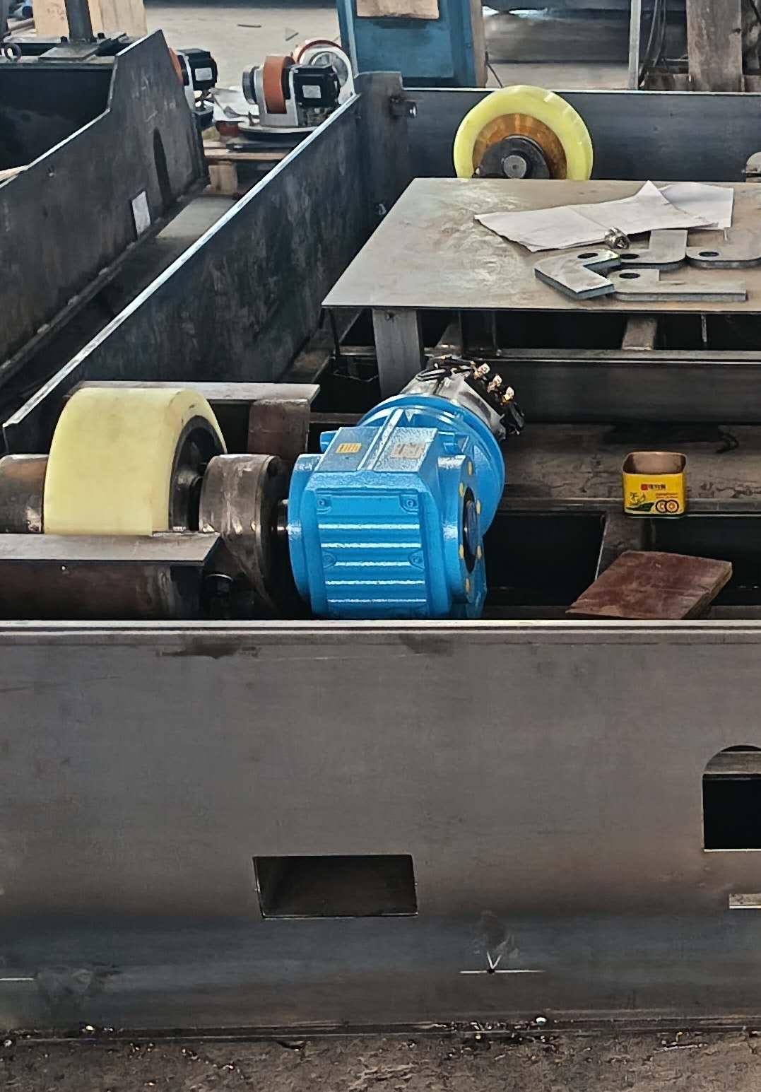
With one AC motor and one gearbox per rear wheel, the only thing keeping the two wheels at the same speed is the controller telling both motors the same rpm. That is an instruction, not a constraint. Several things can make the two wheels disagree in practice:
- Wheel slip goes undetected. When one wheel loses grip on gravel, it spins faster than the cart is moving. The encoder reports a healthy speed because the encoder measures the wheel, not the ground. The controller sees nothing wrong while the cart curves toward the wheel that still has grip.
- Parameter and tolerance differences. Two drives of the same model still differ slightly in how they interpret a command, and two motors still differ slightly in speed at the same command. Small differences accumulate over distance. A cart that is one percent off crab-walks half a metre over fifty metres.
- Load-dependent speed droop. When the centre of gravity shifts, the heavily loaded wheel needs more torque. A drive running a speed loop will try to hold rpm, but once it reaches its current limit the speed falls anyway. The cart steers toward the slow wheel.
The important point is that none of this is a fault you can repair. It is how independent-wheel drive behaves when the ground stops being uniform.
Polyurethane wheels are the wrong tyre for a bad floor
Polyurethane is a hard, wear-resistant material, and that is exactly why it is popular indoors: low rolling resistance, no marking, long life on smooth concrete. The same hardness works against you outside.
A hard wheel has a narrow contact patch. On a flat floor that is fine. Over a slab joint, a gravel stone, or a drain cover, a small-diameter hard wheel climbs the obstacle or stops against it instead of deforming around it. When one wheel stops climbing while the others keep rolling, that corner lifts, load transfers to the diagonally opposite wheel, and the cart yaws. Do that twice a second at walking pace and the operator feels it as a cart that will not settle.
Casters follow the floor, they do not hold a line
A caster has no steering command. It points wherever the combination of rolling direction and ground friction pushes it. On a cambered yard, that means the front of the cart follows the camber. Over a patch of loose material, it follows the material. The operator is not steering a cart with a caster at the front; the operator is negotiating with the floor.
There is a second cost that shows up later. A heavily loaded caster needs a large offset and a stiff swivel to start turning, and a large offset is what produces shimmy at speed. On a 5-tonne cart, that trade is hard to win.
Off-centre loads move the problem onto one wheel
Four wheels share the load only when the centre of gravity sits between them. Move the load toward one corner and that wheel's share rises. With independent drive, that wheel also becomes the one that needs the most torque and the one most likely to reach its current limit first. The cart then steers toward it.
On this cart the nominal share is 1.25 tonnes per wheel — 5 tonnes over four wheels. An off-centre load can push a single corner well above that, and the drive on that corner has no way to ask the other three for help.
The change: one axle instead of two motors
The redesign did not add power. It removed the freedom for the two sides to disagree.
A differential rear axle replaces two independent wheel drives
The new cart drives through a heavy-truck-type rear axle with an integrated differential, a single traction motor, and an R77 helical gearbox. Both rear wheels are now geared to the same housing.
That singles change fixes the steady-state error. A differential does two things at once: it lets the two wheels turn at different speeds when the cart corners, and it keeps them geared to a common input when the cart runs straight. There is no encoder to disagree with another encoder, no parameter set to fall out of step, and no accumulated drift, because the relationship between the wheels is set by gear teeth rather than by software.
It is worth being honest about the trade. A differential delivers equal torque to both wheels, so if one wheel loses grip entirely, the axle will spin that wheel and the cart will not move. That is a real limitation. It is managed here in two ways. The tyres and the wheel loading make total loss of grip on one side unlikely on the floors this cart is built for. And where the route includes genuinely bad ground, the axle can be specified with a limited-slip or locking differential. What the differential does not do is wander while both wheels have grip, which is the failure the customer was living with.
23x10-12 solid rubber tyres replace polyurethane
The wheels are now 23x10-12 solid rubber tyres, four of them. Read the size as 23 inches overall diameter, 10 inches section width, 12 inch rim — about 584 mm across.
Two things change with that. First, diameter. A 584 mm tyre rolls over a slab joint or a stone that a small hard wheel would have to climb, and it does so without lifting the corner. Second, compliance. Rubber deforms around an obstacle instead of stopping against it, so the contact patch stays loaded and the drive stays connected to the ground. Solid rubber rather than pneumatic means no punctures and no pressure checks in a factory yard.
The larger contact patch also lowers ground pressure. The same 1.25 tonnes per wheel, spread over a wider footprint, leaves less of a mark on the floor and puts less demand on the surface.
Hydraulic steering on a front axle replaces casters
The front is now a steering axle with a hydraulic cylinder, a 1.0 kW steering motor and a pump station. The operator commands an angle; the axle goes to that angle and stays there.
This is the part that changes the driving experience most. The cart no longer negotiates with the floor — the front wheels point where they are told, and a camber no longer steers the cart. Because the front axle steers as an axle rather than each wheel swivelling freely, the wheels also follow a proper turning geometry instead of scrubbing sideways through every corner. On a 5-tonne cart with hard wheels, that scrubbing was wearing the tyres and loading the drive.
What the new cart is
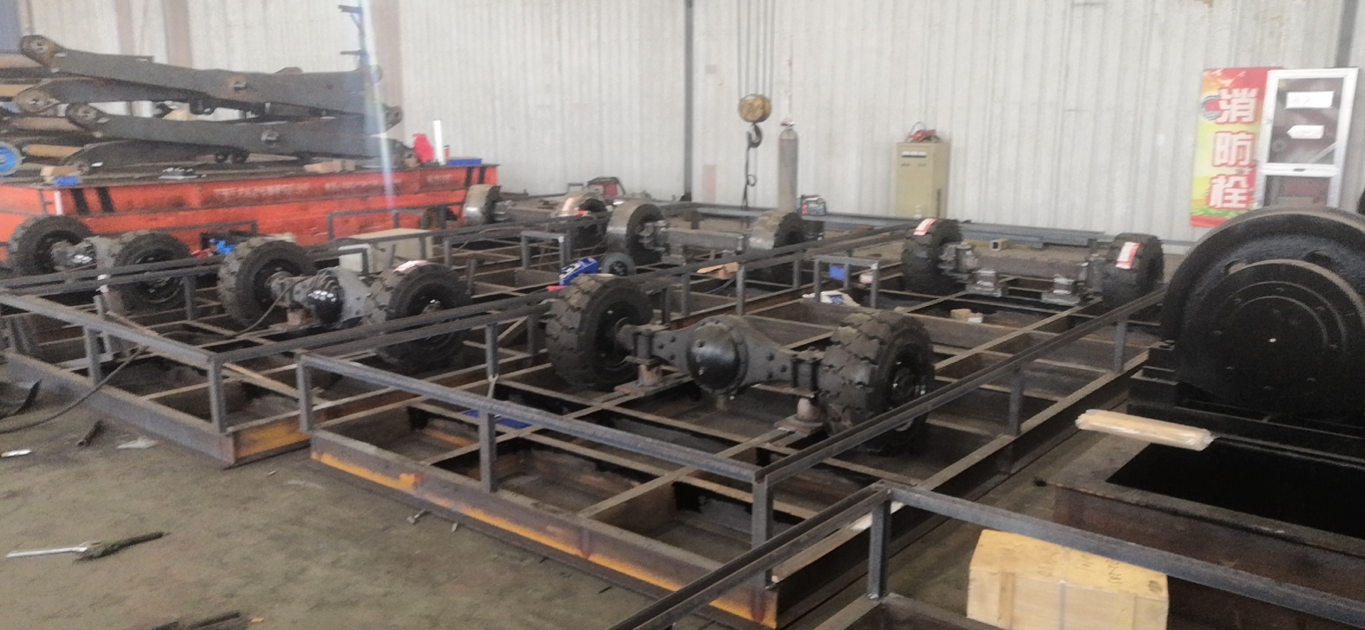
The platform is a trackless electric transfer cart: no rails, no floor preparation, steered by hand or by remote. That category matters for the application, because the customer's routes are not fixed. The cart moves between stations, outside to a yard, and back — a rail cart could not do that job at all, and a forklift could not carry a 3-tonne load of that footprint.
| Item | Original layout | Revised layout |
|---|---|---|
| Drive | Two independent drive wheels, one motor and gearbox each | Heavy-truck rear axle with differential, one motor, R77 gearbox |
| Steering | Two polyurethane casters, unpowered | Front steering axle, hydraulic cylinder, 1.0 kW pump motor |
| Tyres | Polyurethane | 23x10-12 solid rubber, four wheels |
| Straight-line reference | Two encoders asked to agree | One geared axle |
| Behaviour on a bad floor | Wanders, needs constant correction | Holds heading; the operator steers, the floor does not |
| Behaviour under off-centre load | Pulls toward the loaded side | Load shifts grip, not heading |
The frame is a welded structure of four 16# channel longitudinal beams with cross members, decked in 6 mm Q235 plate. Welding follows GB985 and GB986 for groove preparation, and the inspection standard rejects cracks, porosity, undercut deeper than 0.5 mm, and slag on the finished weld. That matters more than it sounds: a 5-tonne cart flexes, and a frame that flexes unevenly will transfer load between corners no matter how good the drive is.
Braking is electromagnetic. At 30 m/min with a 5-tonne load, the specification calls for a stop within 1.0 m in normal operation and within 0.3 m on emergency braking, using the emergency stop on the control box or the handle. Two laser scanners, front and rear, decelerate at 2.5 m and stop at 1.0 m. Bumpers at both ends, four corner emergency stops, and a two-lamp audible-visual alarm system cover the rest.
Motor, controller and battery
The traction motor is the 48V 6.3kW AC asynchronous traction motor XYQ-6.3PC01, a three-phase induction machine rated 6.3 kW at 1450 rpm. It draws 151 A from a 48 V pack, carries an S2-60 min duty rating and an IP54 enclosure, and reports speed through a 64 pulse-per-revolution encoder. The flange is a standard B5 with an integrated temperature sensor.
An induction motor is the right choice here for one reason that matters on a cart: it has no brushes and no commutator to wear, so there is nothing inside the motor that needs a service interval. On a vehicle that runs shifts in a factory yard, that removes the most common scheduled maintenance item on a DC traction motor.
The 10 to 200 Hz frequency range is what lets the same motor creep at docking speed and run at 30 m/min on the open yard without changing gear. The drive is a matched AC motor controller with stepless speed regulation. It provides overcurrent, overvoltage, undervoltage and short-circuit protection, and it interlocks the forward and reverse commands so the two cannot be energised together.
Power comes from a 48 V 230 Ah lithium iron phosphate pack — about 11 kWh — with a 48 V 100 A automatic charger that brings it back in one to two hours. The stated range is 3000 m at rated load. That figure is the project specification for this duty cycle, not an independent test result, so treat it as the design target it is.
The motor comes from the AC traction motor range we build in Changzhou, and the drive is matched to it at the factory. That is a quieter benefit than the mechanical changes, but it removes the situation where a motor from one catalogue is paired with a drive from another and the two are hoped into agreement.
What this design does not do
Three limits are worth stating plainly, because a transfer cart is often asked to do a job it was never built for.
Gradeability is 3 degrees. That is about 5 percent — enough for a sloped apron or a ramped doorway, not enough for a site with real gradients. A 5-tonne cart at 3 degrees is already working; asking it to climb 8 degrees would need a different drivetrain, not a different tyre.
It is not an off-road vehicle. Solid rubber tyres and a differential handle gravel, slab joints and uneven concrete. They do not handle mud, sand, deep potholes, or standing water over the axle line. A yard that floods is a drainage problem, not a cart problem.
It is a low-speed machine. 30 m/min is 1.8 km/h, roughly walking pace. The safety systems — scanner deceleration at 2.5 m, bumper stops, corner e-stops — are designed around that speed. Running the cart faster to save a trip would invalidate the stopping distances in the specification.
Specifications
| Parameter | Value |
|---|---|
| Total loaded weight | 5 t (2 t cart + 3 t payload) |
| Deck size | 4500 x 2400 x 700 mm |
| Travel speed | Up to 30 m/min |
| System voltage | 48 V DC |
| Traction motor | XYQ-6.3PC01, 6.3 kW AC asynchronous, 1450 rpm, 151 A, S2-60 min, IP54 |
| Steering | Hydraulic, front axle, 1.0 kW pump motor |
| Drive axle | Heavy-truck type with differential |
| Gearbox | R77 helical |
| Wheels | 23x10-12 solid rubber, 4 off (approx. 584 mm diameter) |
| Battery | 48 V 230 Ah LiFePO4, approx. 11 kWh |
| Charger | 48 V / 100 A automatic, 1–2 h recharge |
| Range | 3000 m at rated load (project specification) |
| Gradeability | 3 degrees maximum |
| Braking | Electromagnetic; 1.0 m normal stop, 0.3 m emergency, at 30 m/min and 5 t |
| Control | Manual pendant plus wireless remote, stepless speed regulation |
| Safety | Front and rear laser scanners (2.5 m decel, 1.0 m stop), bumpers, four corner e-stops, audible-visual alarms |
Motor data from the XYQ-6.3PC01 datasheet. Platform data from the project specification for this cart. Gearbox ratio not stated in the specification reviewed.
FAQ
Why did the original cart wander on rough ground but not indoors?
Indoors, both drive wheels keep grip, so the two encoders stay close enough to agree. On gravel or a cambered yard, one wheel slips. Its encoder still reports normal speed because it measures the wheel, not the ground, so the controller never sees the error while the cart curves.
Would a bigger motor have fixed it?
No. More power makes the cart accelerate harder; it does not make two independent wheels agree. The error is in the reference, not the effort.
Does a differential not make it worse when one wheel slips?
It does, if one wheel loses grip entirely. That is the known trade. It is managed with tyres and wheel loading, and a limited-slip or locking differential can be specified for routes with genuinely bad ground. The differential removes the steady-state wander, which was the failure here.
Why solid rubber tyres instead of polyurethane?
Diameter and compliance. A 584 mm rubber tyre rolls over joints and stones that a small hard wheel has to climb, and it deforms around an obstacle instead of stopping against it, so the corner stays loaded and the drive stays connected.
Can this cart climb a ramp?
Up to 3 degrees, which is about 5 percent. Beyond that the drivetrain, not the tyre, is the limit. Say so before the ramp is poured.
Conclusion
The customer's cart was not underpowered and the motors were not faulty. It had two wheels with two opinions about how fast to turn, on a surface that kept changing which wheel had grip. Replacing that arrangement with a geared axle, larger rubber tyres and a steered front axle removed the disagreement at its source.
The lesson generalises. When a trackless cart will not hold a line, check how the wheels are tied together before you size a bigger motor. An AGV drive wheel with independent steering is the right answer when you need zero-radius manoeuvring in a tight aisle. A differential axle is the right answer when you need to hold a heading on a floor that is not flat. Choosing between them is a question about the route, not about the budget.
Working on a transfer cart that will not track, or speccing a new one? Send us the loaded weight, the deck size, the route surface and the worst gradient, and we will tell you which drivetrain fits. Contact our engineering team.